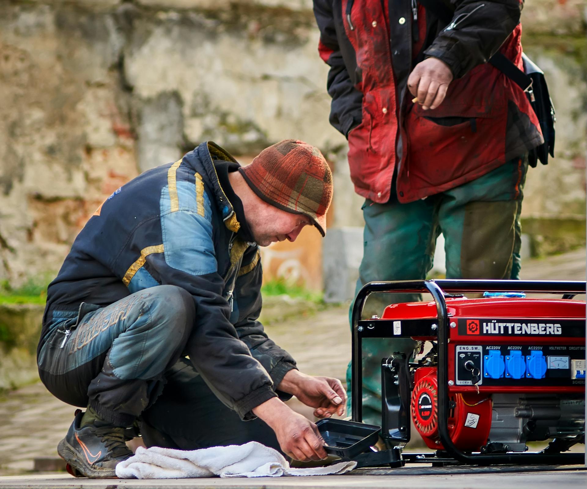
An AC generator is also known as an alternator, and it's a crucial component in many modern devices. The alternator is responsible for converting mechanical energy into electrical energy.
In simple terms, an alternator works by using a magnetic field to induce an electrical current in a wire coil. This process is known as electromagnetic induction. The alternator is essentially a machine that uses rotation to produce electricity.
The alternator is commonly found in vehicles, where it's used to charge the battery and power the electrical systems. It's also used in many industrial applications, such as power generation and distribution.
Here's an interesting read: Ac Power Generator
What is an Alternator
An alternator is a device that converts mechanical energy into AC electrical energy. This is in contrast to a generator, which can produce either AC or DC electrical energy.
An alternator is specifically designed to produce AC electrical energy, making it a type of AC generator. By definition, a generator is a mechanical device that converts mechanical energy to either AC or DC electrical energy.
You might like: Generators Create Electrical Energy.
Alternator Design
An alternator can be designed in two main ways: revolving armature or revolving field. The revolving armature type has the armature wound on the rotor, where the winding moves through a stationary magnetic field.
The revolving field type is more commonly used, as it allows the rotor circuit to carry much less power than the armature circuit, making the slip ring connections smaller and less costly. Only two contacts are needed for the direct-current rotor, whereas a rotor winding with three phases and multiple sections would require multiple slip-ring connections.
The stationary armature can be wound for any convenient medium voltage level, up to tens of thousands of volts.
Consider reading: How Is a Shunt Wound Dc Generator Connected
History
Alternating current generating systems were known in simple forms from the discovery of the magnetic induction of electric current in the 1830s. Rotating generators naturally produced alternating current, but it was normally converted into direct current.
Lord Kelvin and Sebastian Ferranti developed early alternators, producing frequencies between 100 and 300 Hz. This was an important step in the development of AC systems.
Consider reading: Direct Current Electric Generator
The late 1870s saw the introduction of the first large-scale electrical systems with central generation stations to power Arc lamps. These systems were used to light whole streets, factory yards, or the interior of large warehouses.
The Ganz Works invented the constant voltage generator in 1883, which could produce a stated output voltage, regardless of the load. This innovation made AC systems more reliable.
The introduction of transformers in the mid-1880s led to the widespread use of alternating current and the use of alternators needed to produce it. This marked a significant shift towards AC systems.
Later alternators were designed for various alternating current frequencies between sixteen and about one hundred hertz for use with arc lighting, incandescent lighting, and electric motors.
Related reading: Does a Generator Produce Ac or Dc
Simple Generator Structure
A simple generator structure is essential to understand the basics of alternator design. The rotating part of a generator can be either the armature or the magnetic field, as mentioned in Example 2.
The revolving armature type has the armature wound on the rotor, where the winding moves through a stationary magnetic field. This type is not often used due to its complexity.
A simple a.c. generator consists of a rotating coil in a magnetic field connected to an external circuit via slip rings and carbon brushes, as shown in Example 5.
The functions of each component are shown in the following table:
The rotating coil is the heart of a simple a.c. generator, as mentioned in Example 6. It rotates in a uniform magnetic field and is connected to an external circuit via slip rings and brushes.
As the coil rotates, an e.m.f. is induced in it as it cuts the magnetic field. This induced e.m.f. causes an alternating current to be produced in the coil.
The magnitude of the induced e.m.f. can be increased by using a coil rotating in a magnetic field or a magnet rotating within a coil, as mentioned in Example 7.
Alternator Operation
An alternator is essentially an AC generator, and its operation is based on the principle of electromagnetic induction. This principle states that an electromotive force (EMF) is induced in a conductor when it moves within a magnetic field.
The EMF reverses its polarity when the conductor moves under magnetic poles of opposite polarity. In an alternator, a rotating magnet, called the rotor, turns within a stationary set of conductors, called the stator, wound in coils on an iron core.
The rotating magnetic field induces an AC voltage in the stator windings. As the mechanical input causes the rotor to turn, the field cuts across the conductors, generating an induced EMF.
A rotating coil in a uniform magnetic field is the basic setup of an AC generator, including an alternator. The coil is connected to an external circuit via slip rings and brushes, allowing the induced EMF to produce an alternating current.
The direction of the induced current can be determined by Fleming's right-hand rule. As the coil rotates, the direction of the induced current changes after every half of the rotational time period, resulting in an alternating current.
Here's a breakdown of the components involved in an alternator's operation:
The alternator's output voltage is controlled by an automatic voltage control device, which adjusts the field current to keep the output voltage constant. This is particularly important in applications where the output voltage needs to be stable, such as in central power stations.
Alternator Components
The alternator is made up of several key components, each playing a crucial role in generating electricity. The rotor is at the heart of the alternator, consisting of an electromagnet with field windings that create a magnetic field.
A drive belt pulley system spins the rotor on a shaft while the vehicle engine is running, creating a rotating magnetic field. The rotor also has a series of alternating North and South finger pole pieces that wrap around the iron core on the rotor shaft.
The stator is a stationary part of the alternator, consisting of three separate coil windings with one end of each winding connected together. These coil windings are evenly spaced at intervals of 120 degrees around the iron shaft.
The rotor spinning inside the stator causes an induced voltage across the stator windings due to the rotating magnetic field. The faster the magnetic field changes, the more voltage is induced in the stator windings.
Rotor
The rotor is a crucial component of an alternator, and it's fascinating to see how it works. A drive belt pulley system spins the rotor on a shaft while the vehicle engine is running.
At the heart of the rotor is an electromagnet often referred to as field windings. An electromagnet consists of a length of conductive wire wrapped around a piece of magnetic metal. Voltage is applied to the coiled wire creating a current in it. This creates a magnetic field around the coiled wire.
Much like a permanent magnet, there is a North and a South pole. A rotor also has a series of alternating North and South finger pole pieces placed around the field windings that wrap around the iron core on the rotor shaft.
The rotor is designed to spin inside the stator, a stationary part of the alternator.
Rectifier
A diode is a type of rectifier that allows current to flow in one direction only.
In simple terms, a diode has two terminals, the Anode and the Cathode, and will only conduct current if the Anode is more positive than the Cathode.
The Alternator rectifier uses multiple diodes to convert AC to DC, with six diodes being a common configuration.
These diodes are mounted in a heatsinking material to protect them from burning up due to excessive heat.
The diodes in the Alternator rectifier are configured to rectify and convert both half-cycles of every stator voltage AC voltage.
A diode trio output is fed to the voltage regulator after the rectification process.
The six diodes in the Alternator rectifier are used to take advantage of both half-cycles of every stator voltage AC voltage.
Alternator Comparison
An alternator is essentially another name for an AC generator. It converts mechanical energy into AC electrical energy.
The key difference between an alternator and a generator is that a generator can produce both AC and DC electrical energy, whereas an alternator specifically produces AC electrical energy.
A generator, which is often confused with an alternator, is a mechanical device that converts mechanical energy into either AC or DC electrical energy.
An alternator, on the other hand, is a device that converts mechanical energy into AC electrical energy, making it a type of AC generator.
Here's a quick comparison between an alternator and a generator:
In the case of an alternator, the process of converting mechanical energy into AC electrical energy involves a rectangular coil rotating in a uniform magnetic field, connected to an external circuit via slip rings and brushes.
Factors Affecting Alternators
Alternators are a crucial part of many electrical systems, and understanding how they work is essential for their proper functioning.
The magnitude of the induced e.m.f. in an alternator can be increased by several factors.
One way to increase the induced e.m.f. is by using a coil that rotates in a magnetic field.
This setup ensures that the coil will experience a changing magnetic field, resulting in an induced e.m.f.
A magnet rotating within a coil also induces an e.m.f. in the coil as it ensures the coil will experience a changing magnetic field.
Both of these methods are effective in increasing the magnitude of the induced e.m.f. in an alternator.
Here are some key methods to increase the induced e.m.f.:
- a coil rotating in a magnetic field
- a magnet rotating within a coil
Simple Alternator Structure
A simple alternator, also known as an AC generator, is a crucial device in generating electrical power. It consists of a rotating coil in a magnetic field connected to an external circuit via slip rings and carbon brushes.
The slip rings are the key to transferring electrical energy from the rotating coil to the external circuit. They're essentially metal rings that rotate with the coil.
Check this out: Examples of Electrical Generators
The carbon brushes are used to maintain contact between the slip rings and the external circuit. They're made of a soft material that wears down over time, requiring periodic replacement.
Here's a breakdown of the functions of each component:
The rotating coil is the heart of the alternator, and it's where the electrical current is generated.
Alternator Applications
Alternators are used in various applications, including automotive, locomotives, and radio transmission.
In modern automobiles, alternators charge the battery and power the electrical system when the engine is running. They replaced DC dynamo generators with commutators in the 1960s.
Automotive alternators can produce up to 1,200 volts DC, which is used to power the traction motors in diesel-electric locomotives.
The prime mover in diesel-electric locomotives turns an alternator, which provides electricity for the traction motors. The traction alternator typically incorporates integral silicon diode rectifiers.
Here are some key applications of alternators:
- Automotive: Charging batteries and powering electrical systems
- Diesel-electric locomotives: Providing electricity for traction motors
- Radio transmission: Producing radio frequency current
Automotive
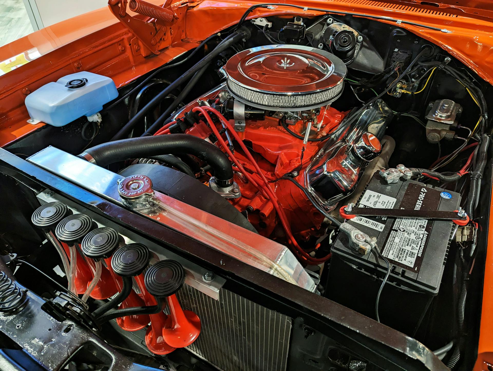
Automotive alternators are used in modern internal combustion engine automobiles to charge the battery and power the electrical system when the engine is running.
Until the 1960s, automobiles used DC dynamo generators with commutators, but with the availability of affordable silicon-diode rectifiers, alternators were used instead.
Alternators have become the standard in modern vehicles, providing a reliable source of power for the electrical system.
Intriguing read: How Do Electrical Generators Work
Radio
Radio applications of alternators involve high-frequency machines that can transmit Morse code, voice, and music. These machines, like the Alexanderson alternator, use a stationary rotor with changing magnetic reluctance to induce current in the armature.
The efficiency of these machines is relatively low, but they were used for radio transmissions in low-frequency bands. In fact, the Alexanderson alternator was a notable example of this technology.
These machines were used to produce radio frequency current for radio transmissions.
Take a look at this: List of Construction Machines
Sources
- https://en.wikipedia.org/wiki/Alternator
- https://www.realpars.com/blog/alternator
- https://www.aopa.org/training-and-safety/students/solo/special/alternators-and-generators
- https://www.savemyexams.com/igcse/physics/cie/23/revision-notes/4-electricity-and-magnetism/4-4-electromagnetic-effects/4-4-3-the-a-c-generator/
- https://www.electricaleasy.com/2014/02/AC-generator-alternator-construction-working.html
Featured Images: pexels.com


