A DC motor can be converted into a generator by simply reversing the flow of current. This is done by removing the motor's armature and replacing it with a commutator.
The commutator is a critical component in a DC generator, as it helps to switch the current flow to the correct direction. It's essentially a rotating switch that allows the generator to produce a steady output.
The armature in a DC generator is made up of a large number of turns of wire that are mounted on a rotating core. This core is typically made of a ferromagnetic material, such as iron or steel.
By converting a DC motor into a generator, you can harness the energy generated by the motor's rotation and use it to power electrical devices.
On a similar theme: Direct Current Electric Generator
Machine Construction
A DC machine, which can be either a generator or a motor, has two basic parts: the stator and the rotor. The stator is made up of a yoke, poles, and pole shoes.
The yoke provides mechanical strength and carries the magnetic flux produced by the field winding. It's typically made of cast iron or steel.
Poles are joined to the yoke and carry field winding, while pole shoes support the field coils and spread out the flux uniformly. The field coils are usually made of copper and are wound in a way that forms alternate North and South poles.
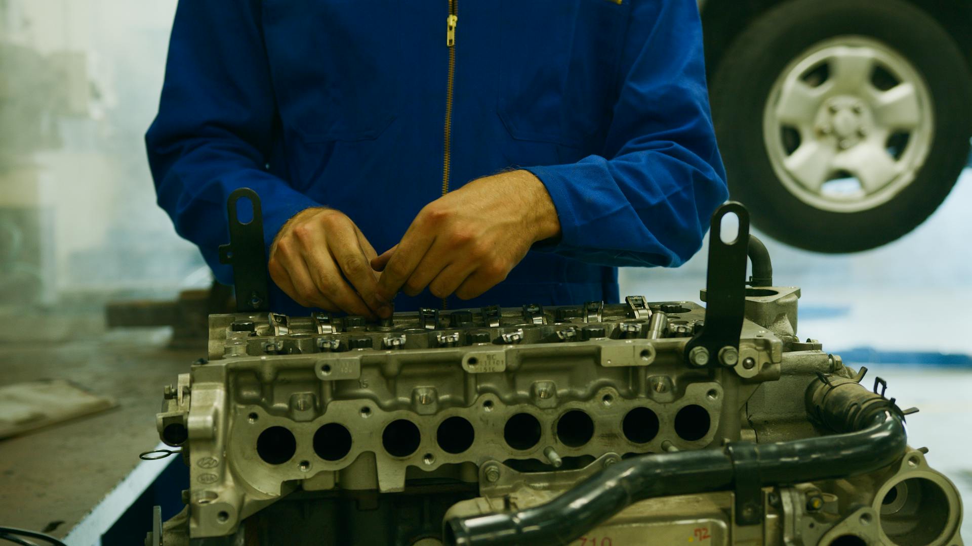
The rotor, or armature core, is cylindrical in shape with slots for the armature winding. It's built up of thin laminated circular steel disks to reduce eddy current losses and may be provided with air ducts for cooling purposes.
The armature winding is a former wound copper coil that rests in armature slots, insulated from each other and the armature core. It can be wound using lap or wave winding, with double layer lap or wave windings being commonly used.
For another approach, see: How Is a Shunt Wound Dc Generator Connected
Machine Construction Details
A DC machine consists of two basic parts: the stator and the rotor. The stator is the outer frame of the machine, also known as the yoke, which is made up of cast iron or steel.

The yoke provides mechanical strength to the whole assembly and carries the magnetic flux produced by the field winding. It's a crucial part that holds everything together.
The rotor, on the other hand, is the armature core, which is cylindrical in shape with slots to carry armature winding. The armature core is built up of thin laminated circular steel disks to reduce eddy current losses.
The armature core may be provided with air ducts for axial air flow to cool the machine. This is especially important in high-power applications.
Here are the basic constructional parts of a DC machine:
- Yoke: The outer frame of a DC machine.
- Poles and pole shoes: Carry field winding and spread out the flux in the air gap uniformly.
- Field winding: Usually made of copper and wound in such a way that they form alternate North and South poles.
- Armature core: The rotor of a DC machine, built up of thin laminated circular steel disks.
- Armature winding: Usually a former wound copper coil that rests in armature slots.
- Commutator and brushes: Physical connection to the armature winding, made through a commutator-brush arrangement.
Short-Shunt Compound
Short-Shunt Compound DC Generators use the shunt field winding in parallel with the armature winding, as seen in the picture below.
The series field current is equal to the load current, Isc = IL.
The shunt field current is calculated using the formula Ish = (V + Isc Rsc)/Rsh.
Armature current is equivalent to the equation V = Eg-Ia Ra-Isc Rsc.
The power load is calculated by multiplying the voltage by the load current, PL = V x IL.
If this caught your attention, see: Shunt Generator
Internal
The internal characteristics of a DC generator are influenced by its armature response, causing the magnetic flux to be lower under loaded conditions than at no-load. This results in a lower generated EMF (E) when the generator is loaded, compared to the EMF produced with no load (E0).
The internal characteristic curves are somewhat lower than the open circuit characteristics due to this difference in magnetic flux.
In a DC generator, the internal characteristics are affected by the relationship between the produced EMF (E) and armature current. This relationship is depicted in the graph, showing how the generated EMF (E) is lower under loaded conditions.
Magnetic Field System
The magnetic field system in a DC generator is its stationary component, generating the primary magnetic flux. It's made up of a large number of pole cores fastened to the yoke with field winding coiled around the pole core.
The pole cores are constructed of thin, insulated sheet steel laminations to prevent eddy current loss, and the field coils are linked in series to create alternating north and south poles in the rotating direction as the current flows through them.
The shaft shoe has two objectives: it provides support for the field coils and lowers the reluctance of a magnetic circuit by expanding its cross-sectional area.
Here are the key functions of the shaft shoe:
- Provides support for the field coils.
- Lowest the reluctance of a magnetic circuit by expanding its cross-sectional area.
Magnetic Field System Overview
The magnetic field system in a DC generator is its stationary component, responsible for generating the primary magnetic flux. It's made up of a large number of pole cores attached to a yoke with field winding coiled around them.
The field arrangement features prominent poles, such as those that thrust inwards, and each pole core has a post shoe with a curved surface. The shaft shoe serves two purposes: it provides support for the field coils and lowers the reluctance of the magnetic circuit by expanding its cross-sectional area.
To prevent eddy current loss, the pole cores are constructed of thin, insulated sheet steel laminations. The field coils are linked in series to create alternating north and south poles in the rotating direction as the current flows through them.
The magnetic field system's design helps to minimize losses and maximize efficiency. By expanding the cross-sectional area of the magnetic circuit, the shaft shoe reduces the reluctance, allowing for smoother operation.
Here are the key components of the magnetic field system:
- Pole cores: made of thin, insulated sheet steel laminations to prevent eddy current loss
- Field winding: coiled around the pole core to generate the magnetic flux
- Post shoe: with a curved surface, attached to each pole core
- Shaft shoe: provides support for the field coils and lowers the reluctance of the magnetic circuit
External
The external characteristics of a magnetic field system are a crucial aspect to understand. The plot of load current against terminal voltage is referred to as the external characteristics or load characteristics.
This plot shows the relationship between load current and terminal voltage. The terminal voltage is not less than the produced voltage due to armature and series field copper losses.
The equation V = E-Ia (Ra + Rse) explains the voltage drop caused by copper losses in the machine. This results in the exterior characteristics curve being lower than the internal characteristics curve by an amount equal to the voltage drop.
The external characteristics are also known as load attributes and terminal characteristics. They show the connection between load current and terminal voltage.
The voltage drop caused by armature resistance is what makes the external characteristics lower than the internal characteristics. This can be seen in the equation V = E-Ia Ra.
Frequently Asked Questions
How much electricity can a DC motor generate?
A DC motor's power output depends on its current-carrying capacity, with higher current coils generating more power. For example, a 12v DC motor with a 3A capacity can produce 36W of power.
How to turn a DC motor into a generator?
Convert a DC motor into a generator by applying mechanical input through the shaft, causing it to generate electricity. This process is reversible, allowing you to also use electrical input to produce mechanical output
Can all DC motors be used as generators?
Most DC motors can be used as generators, but their design and operation may require special consideration
Sources
- https://www.britannica.com/technology/electric-generator/Direct-current-generators
- https://www.electricaleasy.com/2022/09/construction-and-working-of-dc-generator.html
- https://www.geeksforgeeks.org/construction-and-working-of-a-dc-generator/
- https://www.javatpoint.com/dc-generators
- https://www.myprojectcircuits.com/materials/free-electricity-generator-using-dc-motor/
Featured Images: pexels.com

